
Chapter 11: Installation & Debugging
Installation requirements, step-by-step procedures, commissioning checklists, and troubleshooting guides
11.1 Installation Requirements
Correct installation is the foundation of reliable LPR/ANPR system performance. The installation requirements image below illustrates the critical geometric, environmental, and infrastructure requirements that must be satisfied before any camera is mounted. These requirements are non-negotiable — failure to meet them will result in degraded recognition accuracy that cannot be compensated by software tuning.
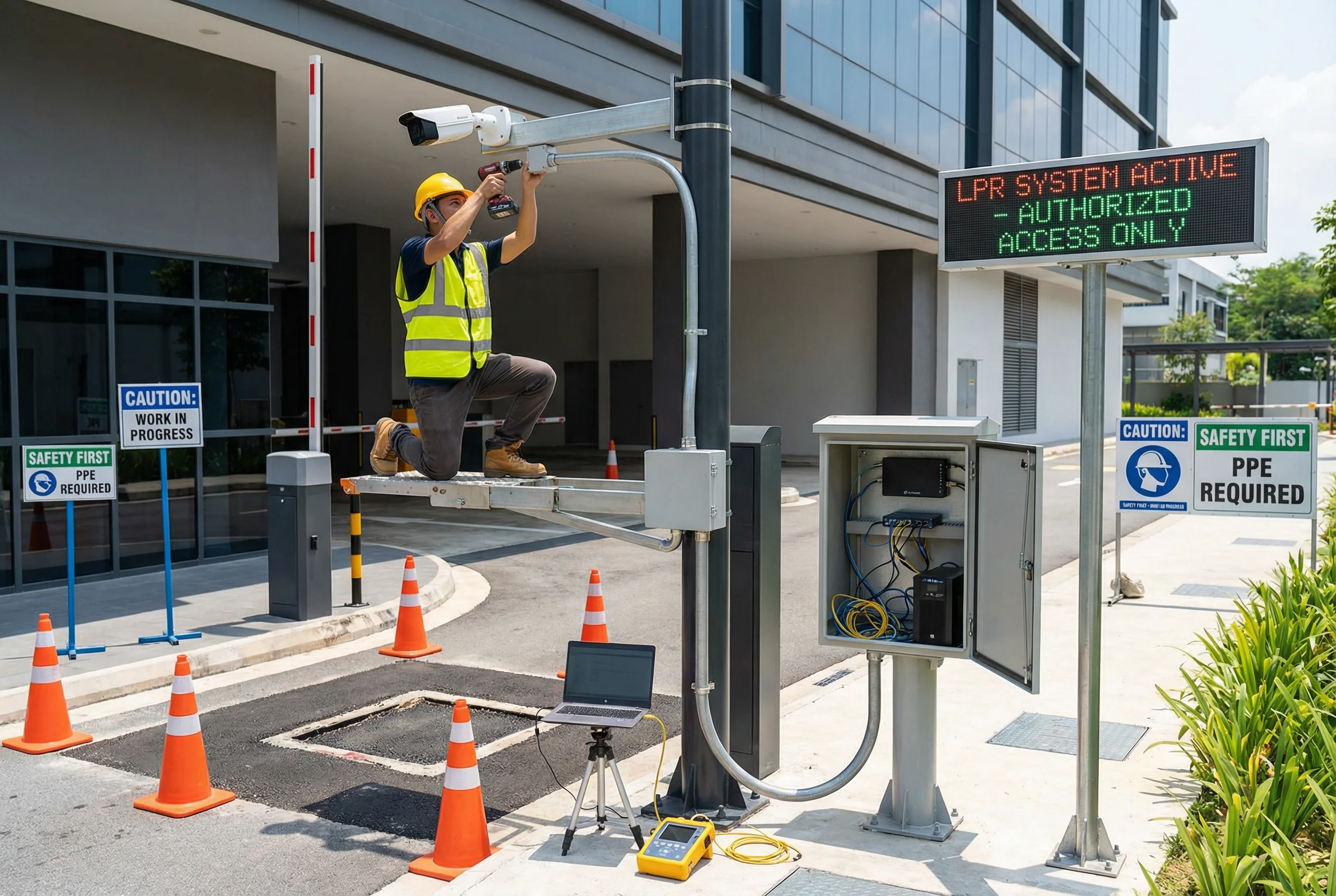
Figure 11.1: LPR/ANPR installation requirements — mounting geometry, cable management, environmental protection, and infrastructure requirements
The installation requirements fall into four categories: Geometric Requirements (mounting height, horizontal angle, vertical angle, capture distance); Environmental Requirements (enclosure rating, temperature range, vibration tolerance, cable entry sealing); Power Requirements (voltage tolerance, PoE standard compliance, surge protection, grounding); and Network Requirements (cable category, maximum run length, connector quality, shielding continuity). All four categories must be satisfied simultaneously — a perfect geometric installation on an inadequate power supply will still fail.
11.2 Mounting Geometry Specifications
Mounting geometry is the most critical installation parameter. Even small deviations from the optimal geometry can significantly reduce recognition accuracy. The following table defines the acceptable ranges for each geometric parameter, with the optimal value and the maximum allowable deviation.
| Parameter | Optimal Value | Acceptable Range | Maximum Deviation | Impact of Deviation |
|---|---|---|---|---|
| Mounting Height | 2.5–3.5m | 2.0–4.5m | ±0.5m from optimal | Increased vertical angle, reduced plate resolution |
| Horizontal Angle | 0° (perpendicular) | 0°–25° | 30° maximum | Keystoning, reduced character separation |
| Vertical Angle | 5°–15° depression | 0°–25° | 30° maximum | Perspective distortion, reduced plate pixel height |
| Capture Distance | Per lens calculation | ±20% of design | ±30% of design | Under/over-resolved plate, incorrect exposure |
| Illuminator Offset | 0.5–1.0m from camera | 0.3–1.5m | 2.0m maximum | Uneven illumination, hotspots, shadows |
| Trigger Position | 3–5m before camera | 2–8m before camera | 10m maximum | Missed triggers, incorrect vehicle association |
11.3 Step-by-Step Installation Procedure
Follow this procedure in sequence. Do not skip steps or perform them out of order. Each step must be completed and verified before proceeding to the next. Record the result of each step in the installation log.
- 1
Site Survey and Preparation
Verify mounting locations match design drawings. Confirm power supply availability and capacity. Check network connectivity to field switch location. Mark cable routes and confirm conduit paths are clear. Verify civil works (foundations, poles, conduit) are complete and cured.
- 2
Cable Installation
Pull STP Cat6 cable through conduit from camera location to field switch. Leave 1m service loop at each end. Install RS-485 cable for barrier gate and trigger devices. Label all cables at both ends using permanent outdoor-rated labels. Seal all conduit entries with appropriate glands and sealant.
- 3
Field Cabinet and Power Installation
Mount field cabinet at approved location. Install PoE switch, UPS, and surge protectors per design. Connect AC power supply with proper grounding. Verify UPS charges and provides correct output voltage. Install surge protectors on all Ethernet and RS-485 cable entries.
- 4
Camera and Illuminator Mounting
Mount camera bracket at calculated height and position. Attach camera to bracket — do not fully tighten until alignment is complete. Mount illuminator on separate bracket at specified offset from camera. Connect all cables — do not power on until all connections are verified.
- 5
Trigger Device Installation
Install inductive loop detector or radar trigger at specified position. Connect trigger output to camera GPIO or field switch. Verify trigger signal polarity and timing with multimeter. Test trigger activation with a test vehicle before proceeding.
- 6
Power-On and Initial Configuration
Power on field switch first, then cameras and illuminators. Verify all devices obtain IP addresses via DHCP or static assignment. Access camera web interface and set basic parameters (IP, NTP, RTSP). Verify video stream is accessible from management workstation.
- 7
Geometric Alignment and Optical Tuning
Position a test vehicle at the design capture point. View live image on laptop at camera location. Adjust pan, tilt, and zoom to achieve correct plate position and size. Verify horizontal and vertical angles are within specification. Tighten all bracket fasteners to specified torque. Apply thread-locking compound to all outdoor fasteners.
- 8
Exposure and Illumination Tuning
Set shutter speed per Chapter 9 calculator result for target vehicle speed. Adjust illuminator intensity for correct plate brightness (130–180 average pixel value). Verify WDR settings handle high-contrast lighting conditions. Test both day and night capture conditions before sign-off.
11.4 Troubleshooting Guide
The following troubleshooting guide covers the most common installation and commissioning issues. Follow the diagnostic steps in order — do not skip to advanced diagnostics before completing basic checks.
| Symptom | Probable Cause | Diagnostic Steps | Resolution |
|---|---|---|---|
| Camera not accessible on network | IP conflict, cable fault, PoE budget exceeded | Check PoE switch port status LED; test cable with tester; verify IP assignment | Resolve IP conflict; replace cable; reduce PoE load |
| Overexposed plate in daylight | Shutter speed too slow; WDR not enabled; IR illuminator on during day | Check shutter speed setting; verify WDR mode; check illuminator schedule | Increase shutter speed; enable WDR; set illuminator to night-only |
| Dark plate at night | Illuminator not triggering; illuminator range insufficient; shutter too fast | Verify illuminator power and trigger signal; measure illumination at plate | Check illuminator wiring; replace with higher-power unit; reduce shutter speed |
| Motion blur on plate | Shutter speed too slow for vehicle speed | Calculate required shutter speed using Chapter 9 calculator; check current setting | Reduce shutter speed to calculated value; verify illuminator provides sufficient light |
| Low recognition accuracy (<90%) | Plate too small (<140px); excessive angle; poor focus; insufficient contrast | Measure plate pixel width in captured image; check angle; verify focus | Adjust focal length or capture distance; realign camera; clean lens |
| Trigger not firing | Loop detector wiring fault; radar sensitivity too low; GPIO polarity wrong | Test loop detector with multimeter; verify radar LED status; check GPIO polarity | Rewire loop detector; adjust radar sensitivity; invert GPIO polarity in config |
| Integration not receiving events | API endpoint wrong; firewall blocking; authentication failure | Check API URL and credentials in camera config; verify firewall rules; test with curl | Correct API configuration; update firewall rules; renew API credentials |