
Chapter 2: Design Methods
Systematic approach to LPR/ANPR system design — from requirements to deployment
2.1 Design Philosophy and Principles
LPR/ANPR system design is fundamentally different from general CCTV design because recognition accuracy is the primary success metric, not just image quality. A system that produces beautiful video but fails to recognize plates reliably is a failed system. The design methodology must therefore work backwards from recognition accuracy requirements to derive all other specifications: pixel density → lens focal length → mounting geometry → illumination → trigger timing → network bandwidth → storage capacity.
The four core design principles are: Capture Chain First (optimize every element in the image capture path before addressing software); Evidence Grade (every design decision must support forensic admissibility); Defense in Depth (redundancy at every critical point — power, network, storage, recognition); and Operational Sustainability (design for the maintenance team, not just the installation team).
2.2 Design Decision Framework
The following decision tree guides the system designer through the key choices that determine system architecture, component selection, and performance targets. Each decision node has defined inputs, outputs, and validation criteria.
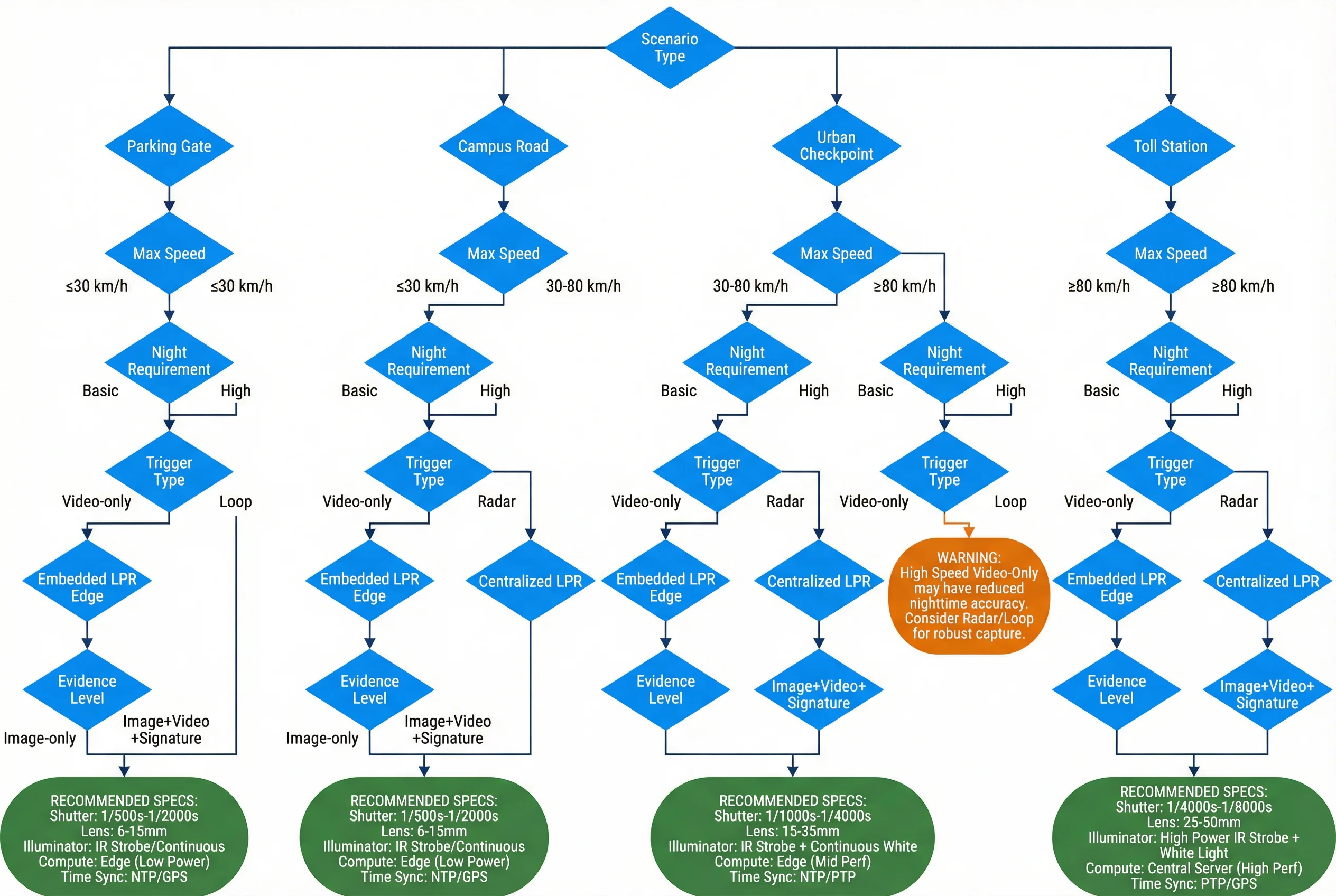
Figure 2.1: LPR/ANPR system design decision tree — from scenario requirements to component specification
2.3 Requirements Capture
Effective requirements capture is the foundation of successful LPR deployment. Requirements must be gathered across four dimensions: functional requirements (what the system must do), performance requirements (how well it must do it), operational requirements (how it will be maintained), and compliance requirements (what regulations it must satisfy).
| Requirement Category | Key Questions | Typical Acceptance Criteria | Validation Method |
|---|---|---|---|
| Recognition Accuracy | Day/night targets? Plate types? Vehicle speeds? | ≥98% day, ≥95% night on controlled test set | Controlled test with 1000+ plates |
| Throughput | Peak vehicles per hour per lane? Burst capacity? | ≤500ms per event at peak load | Load test with simulated traffic |
| Availability | Required uptime? Maintenance windows? | ≥99.5% monthly uptime | Monitoring dashboard, SLA report |
| Retention | How long must events and video be stored? | Events: ≥90 days; Video: ≥30 days | Storage audit, retrieval test |
| Integration | Which downstream systems must receive events? | API response <200ms, 99.9% delivery | Integration test, message queue audit |
| Compliance | GDPR, local privacy law, data residency? | Data encrypted at rest and in transit | Security audit, penetration test |
2.4 Optical Design Methodology
The optical design is the most technically demanding aspect of LPR system design. The goal is to achieve a minimum plate pixel width of 140 pixels (standard recognition) or 200+ pixels (high accuracy) at the capture point. The design process follows a strict sequence: define capture distance → select sensor size → calculate required focal length → verify field of view → confirm illumination coverage → validate with test images.
Key formula: Focal Length (mm) = [Sensor Width (mm) × Capture Distance (m) × 1000] ÷ [Plate Width (mm) × Coverage Factor]. Use the interactive Calculator (Chapter 9) to compute this automatically for your specific parameters.
| Sensor Size | Sensor Width (mm) | Typical Resolution | Best For |
|---|---|---|---|
| 1/2.8" | 5.37 | 2MP–5MP | Standard LPR, cost-effective |
| 1/2" | 6.40 | 5MP | Improved low-light performance |
| 1/1.8" | 7.18 | 5MP–8MP | High-accuracy, wide-angle applications |
| 1/1.2" | 8.80 | 8MP–12MP | Multi-lane, long-range applications |
2.5 Illumination Design
Illumination is the most commonly underspecified element in LPR system design. The illuminator must provide uniform, sufficient light at the plate surface without causing glare to drivers or overexposure to the camera. Key design parameters include wavelength selection (850nm visible IR vs 940nm covert IR), beam angle (narrow for long range, wide for close range), power (matched to capture distance and camera sensitivity), and synchronization (strobe pulse duration must be ≤ camera shutter speed).
2.6 Network and Storage Design
Network and storage design must be driven by calculated bandwidth and capacity requirements, not by rule-of-thumb estimates. The key inputs are: number of lanes, camera bitrates (main and sub streams), LPR event rate, snapshot sizes, video retention period, and RAID overhead. Use the storage and bandwidth calculators in Chapter 9 to derive precise requirements for your deployment.