
Chapter 4: Architecture Design
Typical system topology, device wiring diagrams, and architecture design principles
4.1 Typical System Topology
The reference topology for an LPR/ANPR system follows a hierarchical three-tier model that balances performance, resilience, and maintainability. The topology is designed to support both centralized and distributed recognition architectures, with clear demarcation points for network segmentation, power distribution, and management access.
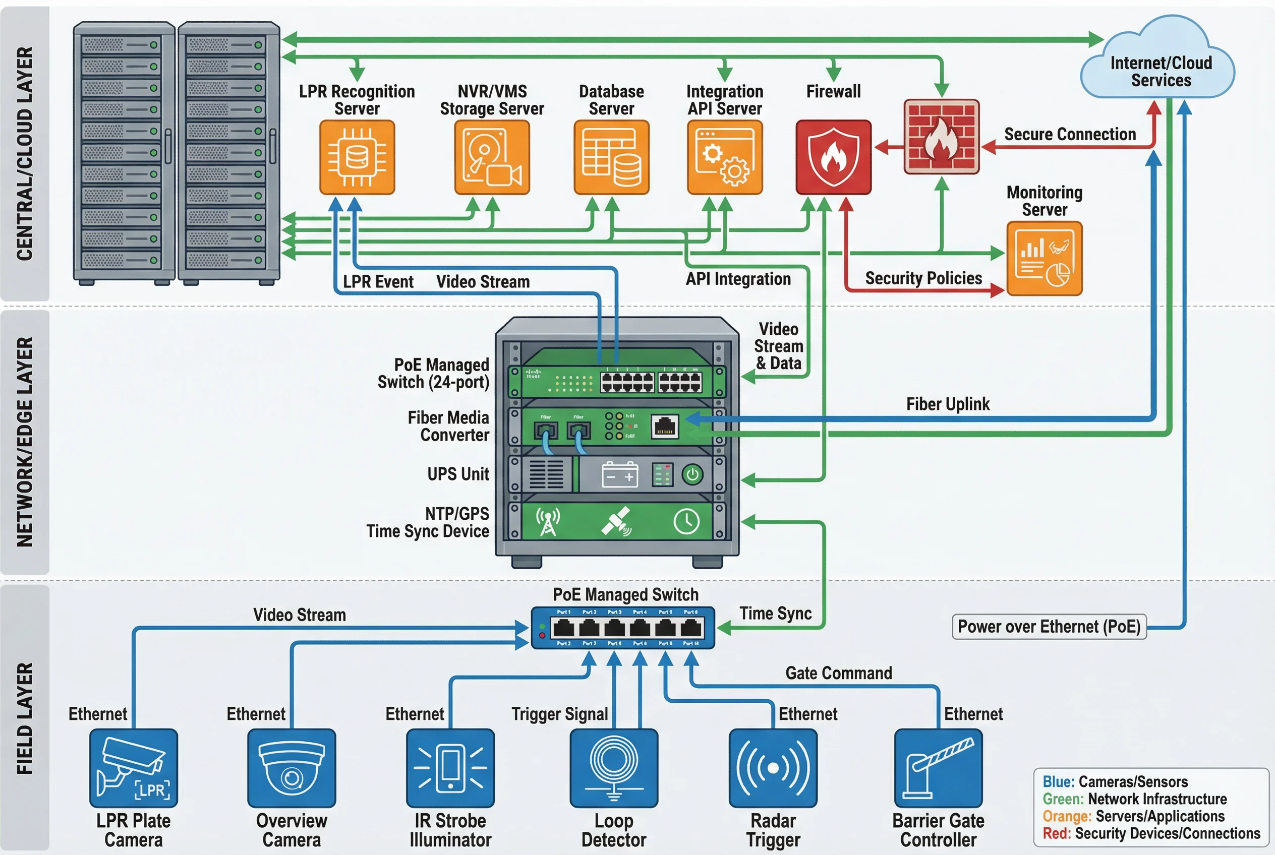
Figure 4.1: Typical LPR/ANPR system network topology — three-tier hierarchical architecture with VLAN segmentation
The topology separates the field device network (VLAN 10: cameras, illuminators, triggers) from the management network (VLAN 20: NVRs, servers, workstations) and the integration network (VLAN 30: API gateway, downstream systems). This segmentation prevents lateral movement in the event of a device compromise and allows independent QoS policies for each traffic class.
Design rule: Never connect LPR cameras directly to the corporate LAN. Always use a dedicated, VLAN-segmented network with firewall rules that permit only the required protocols (RTSP, ONVIF, HTTPS) on defined ports.
4.2 Device Wiring and Connection Diagram
The device wiring diagram illustrates the physical connections between all field components at a single lane capture point. Understanding these connections is essential for correct installation, troubleshooting, and maintenance. The diagram shows power distribution, signal connections, and communication interfaces for a complete single-lane LPR deployment.
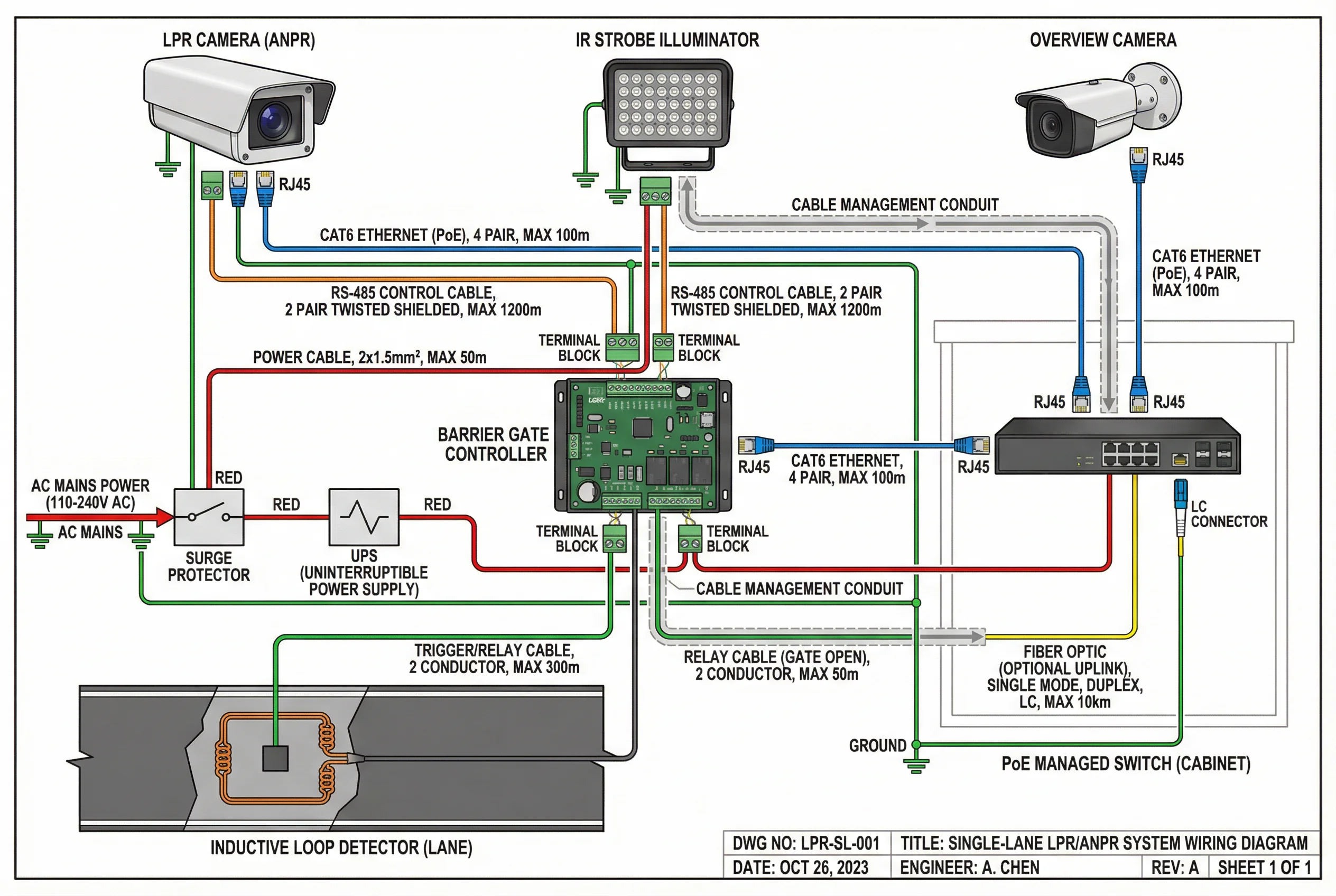
Figure 4.2: LPR lane device wiring diagram — power distribution, signal connections, and communication interfaces
Key wiring principles: all outdoor cable runs must use shielded cable (STP Cat6 or better) with proper grounding at one end only to prevent ground loops; power cables must be sized for the maximum PoE budget plus 20% margin; RS-485 cables for barrier gate control must be twisted pair with 120Ω termination resistors at both ends; and all junction boxes must be rated IP66 or better with cable glands for each entry point.
4.3 Architecture Design Principles
The architecture must be designed to meet the following non-functional requirements: High Availability (redundant power, network paths, and storage); Scalability (ability to add lanes without redesigning the core infrastructure); Security (defense-in-depth with network segmentation, authentication, and encryption); Maintainability (remote management, automated health monitoring, and clear escalation paths).
| Architecture Layer | Redundancy Requirement | Failover Time | Recovery Procedure |
|---|---|---|---|
| Power (Field) | UPS + surge protection per cabinet | Automatic (0ms) | UPS battery replacement per schedule |
| Network (Access) | Dual uplinks from field switch to core | <50ms (STP/RSTP) | Replace failed switch, restore config from backup |
| Storage (Edge) | RAID-1 minimum on edge NVR | Automatic (0ms) | Hot-swap failed drive, rebuild RAID |
| Recognition Engine | Active-passive cluster | <30s | Automatic failover, alert NOC |
| Management Platform | Active-active with load balancer | <5s | Automatic, health check triggers failover |
| Database | Primary + replica with automated failover | <60s | Promote replica, reconfigure application |
4.4 Network Design Specifications
Network design must account for the aggregate bandwidth of all cameras (main stream + sub stream), LPR event data (images + metadata), management traffic, and NTP synchronization. The field switch must have sufficient PoE budget for all connected devices at maximum power draw, with at least 20% headroom for future expansion.
| Traffic Type | Per-Lane Bandwidth | Protocol | QoS Priority |
|---|---|---|---|
| LPR Camera Main Stream | 4–8 Mbps | RTSP/H.265 | High (DSCP EF) |
| Overview Camera Main Stream | 2–4 Mbps | RTSP/H.265 | High (DSCP EF) |
| LPR Event Data (images) | 0.5–2 Mbps | HTTPS/REST | Medium (DSCP AF31) |
| Management & Config | <0.5 Mbps | HTTPS/SSH | Medium (DSCP AF21) |
| NTP Synchronization | <0.1 Mbps | NTP/UDP | High (DSCP EF) |