
Chapter 1: System Components
Core hardware and software elements of an LPR/ANPR video surveillance system
1.1 System Architecture Overview
An LPR/ANPR system is a layered, event-driven architecture that transforms raw video frames into structured, tamper-evident records. The architecture comprises three functional tiers — Field, Edge/Access, and Central — connected by a segmented network fabric. Each tier has clearly defined responsibilities, failure modes, and integration boundaries.
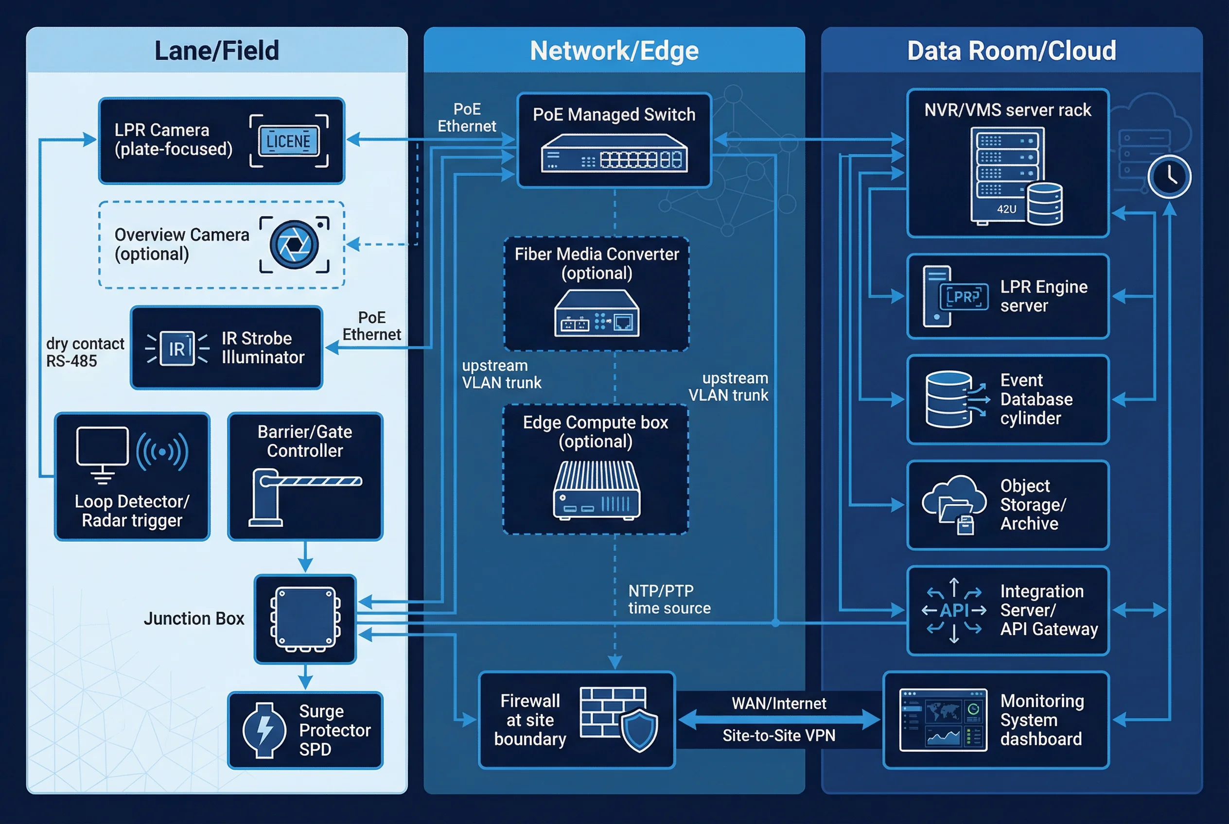
Figure 1.1: LPR/ANPR system architecture — three-tier swim-lane diagram showing Field, Edge/Access, and Central layers
The Field Layer encompasses all physical devices at the capture point: LPR cameras, overview cameras, IR illuminators, trigger devices (loop detectors, radar, video analytics triggers), mounting poles, junction boxes, and local power distribution. The Edge/Access Layer includes PoE switches, local NVRs or edge servers, time synchronization sources (NTP/PTP/GPS), and VLAN-segmented network infrastructure. The Central Layer hosts the LPR management platform, central NVR/storage cluster, integration middleware (API gateway, message broker), and the security operations center.
1.2 Components and Functions
Each component in the LPR system plays a specific role in the capture-to-evidence pipeline. The following diagram and table provide a comprehensive inventory of system components, their primary functions, key specifications, and typical failure modes.
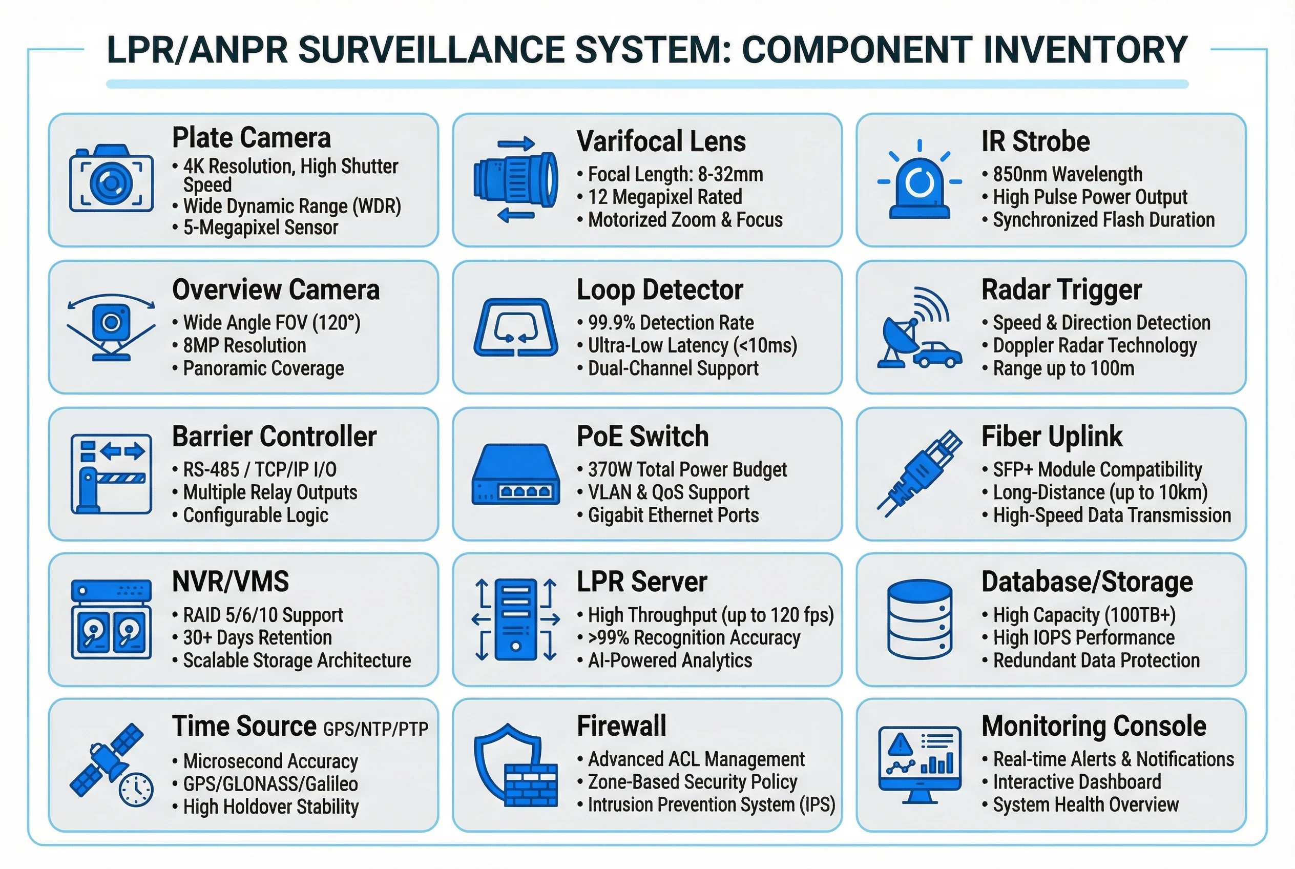
Figure 1.2: LPR system component inventory — functional grouping of all hardware and software elements
| Component | Primary Function | Key Specification | Typical Failure Mode |
|---|---|---|---|
| LPR Camera | Capture plate images with sufficient pixel density for recognition | ≥5MP, global shutter, 1/2.8" sensor, H.265 | Defocus, IR filter switching failure, overexposure |
| Overview Camera | Capture full-vehicle context image for evidence | ≥2MP, wide-angle, WDR ≥120dB | Lens fogging, IR cut filter stuck |
| IR Illuminator | Provide uniform illumination for night capture without glare | 850nm or 940nm, ≥30m range, IP67 | LED aging, power supply failure, beam misalignment |
| Loop Detector | Trigger capture at precise vehicle position | Inductive loop, 1–5ms response, fail-safe output | Loop wire break, sensitivity drift, false triggers |
| Radar Trigger | Non-invasive vehicle detection and speed measurement | 24GHz FMCW, ±2km/h accuracy, 0–200km/h range | Multipath interference, rain attenuation |
| PoE Switch | Power and connect field devices over Ethernet | PoE+ (30W/port), PoE budget ≥240W, managed | PoE budget overload, STP misconfiguration |
| Edge NVR/Server | Local video buffering, edge recognition, event pre-processing | ≥8-channel, RAID-1, ≥4TB, GPU optional | HDD failure, thermal shutdown, RAID degradation |
| LPR Engine (Software) | Recognize plate text from captured images | ≥98% accuracy (day), ≥95% (night), <300ms latency | Model drift, GPU OOM, license expiry |
| Management Platform | Event management, search, reporting, integration | Web-based, REST API, ONVIF, SDK | DB corruption, session timeout, API rate limiting |
| UPS | Maintain power during outages for graceful shutdown | ≥500VA, ≥15min backup at full load, auto-transfer | Battery aging, overload, transfer switch failure |
| NTP/GPS Time Source | Synchronize timestamps across all devices | Stratum 1 GPS or Stratum 2 NTP, <1ms accuracy | GPS antenna obstruction, NTP server unreachable |
| Barrier Gate | Control vehicle access based on LPR events | RS-485 or relay interface, <3s cycle time | Motor failure, communication timeout, power loss |
1.3 Data Flow and Event Lifecycle
Understanding the data flow is essential for designing reliable systems. A complete LPR event follows this sequence: trigger signal received → camera exposure triggered → plate crop and overview image captured → images transmitted to recognition engine → plate text extracted with confidence score → event record created with timestamp, lane ID, and cryptographic hash → event stored in database → integration actions dispatched (gate open, alarm, billing) → audit log written. Each step has defined latency budgets and error handling requirements.
Key design principle: every LPR event record must include a cryptographic hash or digital signature of the plate crop image to ensure evidence integrity. This is mandatory for legal and forensic applications.
| Pipeline Stage | Max Latency Budget | Error Handling | Audit Requirement |
|---|---|---|---|
| Trigger → Capture | <50ms | Missed trigger alarm, retry logic | Trigger timestamp logged |
| Capture → Recognition | <200ms | Queue with overflow protection | Image hash recorded |
| Recognition → Event Record | <100ms | Fallback to manual review queue | Confidence score logged |
| Event → Integration Action | <500ms | Retry with exponential backoff | Action result logged |
| Event → Storage | <1s | Local buffer, sync when online | Storage confirmation logged |